
Here is a gas model that is a contest threat in every sense of the word. It was designed with just one thought in mind—to prove that “pylons” are not necessary. The consistent and high performance this model turns in is a direct result of the constant improvement and refinement that has gone into several models of the same design during the past three years. And the way Pylon Buster behaves under power is a tribute to the engine manufacturers. With so much power available in the present day engines packed into such a slick lob—well, you just can’t go wrong.
The secret to Pylon Buster’s high rate of climb (straight, not spiral) and very flat glide Ices in a very simple yet foolproof tail adjustment mechanism which is hooked on to the ignition timer. After the engine cuts, the elevator moves slightly up and the left rudder turns automatically, resulting in a flat circling glide w die right. Actually, the job has two sets of flight adjustments—one for climbing and one for gliding! The original model was powered with an Atwood Champion engine but the Hornet, McCoy, “OK” 60, Ohlsson 60 or any top displacement class C power plant can be used.

Due to the large size of the model and preponderance of curved parts, it would be wise to obtain full site plans from your hobby shop in order to save time and effort in scaling up the plans presented on these pages.
Wing construction is of the conventional type but the very thin airfoil (Goldberg G-7) and high aspect ratio makes it imperative to exercise the utmost of care when selecting the wood and during actual construction. The front and rear spars are very hard balsa while the tips, leading edge, ribs and trailing edge are of medium grade stock. The wing is built in two halves and then joined. Cut out the ribs and cement them to the lower main spars, which are pinned directly to the plan. Add the trailing edge and then cement the upper spars in place. The leading edge and trailing edge gussets are next cemented in place and the panel removed. The space between the top and bottom spar is now filled with 3/32 in. sheet stock, the panel severed at W-10 and the 3 in. tip dihedral added.
Next, cover the top portion of the leading edge with flexible A in. sheet balsa. Add the solid tips and the cap strips to the top of each rib and then sandpaper the entire panel so all joints are absolutely flush. A length of 18 pound fish line is now cemented along the leading edge and the panel set aside until ready to be joined to the left panel, which is made in precisely the same manner as the right after the outline has been traced through the plan or else on a piece of tracing paper. Once both panels are complete, join them is the prescribed dihedral angle exists. After the dihedral reinforcements are in place, cover the center section with 1/16 in. sheet.

Before covering the wing, apply two coats of clear dope where the covering will touch the wood and then cover with wet Silkspan. Silk, if available, is preferable but double Silkspan (cross-grained) will suffice. Use plenty of water on the Silkspan and when the panel is dry, dope once and add the second layer. Three coats of clear dope or your favorite color will complete the wing.
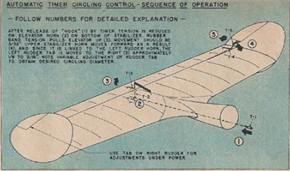
The stabilizer is built in one piece, making it necessary to pin a full length spar and trailing edge to the half shown on the plan. The ribs, trailing and leading edge are assembled over the left half shown on the plan. When the glue has dried, remove the structure from the plan, trace the outline and finish the right half. As mentioned previously, the flight secret of the Pylon Buster lies in the automatic tail control so make certain the elevator movement is easy. Cover the stabilizer with wet Silkspan and then proceed to carve the vertical surfaces, which are cut from 1/4 in. sheet stock and sanded to a streamlined airfoil. Cement fish line around the edge, cover with Silkspan and then cut away the section to be hinged. Cement the fins to the stabilizer and then complete the control system, as detailed in the drawing shown directly above.
After the elevator and rudder horns are in place, hold the elevator in neutral and make adjustments on the horn to the rudder is also in the neutral position. Now move elevator 3/32 in. up. The rudder should turn automatically 1/8 in. to the right. This movement gives the required flat circling glide to desired for high performance. Finally, bend to shape the two horns to be cemented to the center of elevator and lay the assembly aside.
The fuselage, with its unorthodox shape, is very clean and is no more difficult to build than the average bulkhead-type structure. It is made in two sections. the nose unit of which is composed of formers F-1 and F-2, with the aluminum motor mounts acting as a backbone. After this structure has taken shape, add the landing gear details and set aside until the main section is ready for joining.
In making the main section, cut the keels from 1/4 in. hard sheet stock and pin over the plans. Cut out two halves of each bulkhead (unless otherwise indicated) and cement the left half to the keel. After the cement is dry, remove the structure and attach the right bulkhead halves. The two side stringers are now attached, exercising special care so the fuselage does not warp. Add the nose section and then insert 1/4 in. square stringers between formers F-2 and F-4 to form the wing mount.

Installing the automatic tail adjustment mechanism is the next chore. Set a piece of .032 wire on the Austin timer arm, wrap well with thread and cement. Adjust the timer for 24 seconds, mount in place and add the peg and “stops”. The timer extension wire passes through the three “stops” with the controlling hook slipped between. When the timer cuts, the hook is released and the elevator and left rudder assume a new setting for gliding. Adjust the mechanism via trial and error so the engine cuts one or two seconds after the hook is released. Next, set the stabilizer platform in place and then mount the coil and battery box. Better still, use General, Bright Star or Burgess pack batteries and you’ll save yourself ignition troubles. Complete your wiring, as given by your engine manufacturer.
The fuselage is planked with soft 1/8 x 3/8 in. balsa. Start from a point just below the wing mount and work both sides simultaneously. After planking about 2 in. on both sides remove part of the keel between F-2 and F-3 for the wheel. The cowl is made from solid balsa or built-up blocks if necessary. Lay out the side and top views and carve to fit your engine.

Cement the stabilizer in place, add the fillets and plank from F-11 hack. Pin the wing to the fuselage and fit the F-2 to F-5 section to the wing. Plank with care to insure good fit. Insert the dowels or wire rods to hold the wing in place and cut out the doors for battery and control mechanism. Balance your Pylon Buster at a point 50% back from the wing root and glide from a steep incline with the control mechanism hooked up to the elevator and left rudder are neutral. Use right rudder to obtain a slight right circle tendency, just enough to counteract torque. Release the control mechanism, glide the model again and adjust the elevator and rudder setting so a very flat, smooth, circling glide to the right results. While testing at 1/3 power, adjust for a straight power climb or a very right wide circle climb. Increase the power and then—well, bring on the pylon competition!
Resources:
- Mechanix Illustrated, issue – January, 1947
- plan hosted on Outerzone